 Djinious
Arm kinematics
Forward kinematics of the 3-link planar arm, swept to trace the bucket-tip reachable workspace — 11.68 m reach and 6.58 m dig depth, rendered as a 3D pose and a 2D envelope.
The platform
Each application does one part of the work — and hands its evidence to the next. Use them together, or one at a time.
Platform overviewSee how the loop runs DjiniousEngineeringOrchestration
 DjiniousLabModelling & simulation
 DjiniousWorkshopSystem integration
 DjiniousSafeCertifiable code
 DjiniousWorld3D replicas
 DjiniousMapAgent GIS
 DjiniousCCOperations & SCADA
 DjiniousDataKnowledge base
 DjiniousWorkflowAgent automation
A 20-tonne excavator as one multi-physics model — a planar boom/stick/bucket linkage driven by hydraulic cylinders off a load-sensing pump, from kinematics and workspace through a coupled dig cycle to breakout force and cycle energy.
 DjiniousLab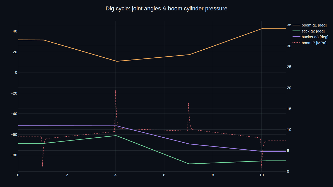
A 20-tonne excavator's working arm — boom, stick and bucket — as one model that spans two physical domains at once: a planar multibody linkage driven by hydraulic cylinders fed from a load-sensing pump. From forward and inverse kinematics through a coupled dig cycle to breakout force and cycle energy, with the valve-controlled cylinder also composed as a runnable acausal .djl over a brand-new hydraulic domain.
Each subsystem is its own runnable notebook, building from arm geometry up to a coupled fluid-and-multibody dig cycle.
Forward kinematics of the 3-link planar arm, swept to trace the bucket-tip reachable workspace — 11.68 m reach and 6.58 m dig depth, rendered as a 3D pose and a 2D envelope.
A closed-form solver places the bucket tip at a target with a 0 mm forward-kinematics round-trip error — exact, not iterative.
Chamber compressibility, orifice valve flow and piston dynamics: a commanded cylinder extends to 0.96 m and peaks at 24 MPa, under the 35 MPa relief.
The cylinder geometry's nonlinear moment arm — peaking near 1.29 m mid-travel — maps cylinder force to a maximum boom-joint torque of 515 kN·m at system pressure.
The planar multibody arm, gravity and inertia included, driven by the three cylinders through a dig trajectory — joint angles, cylinder pressures and bucket path as a 46-frame animation.
One load-sensing pump's flow shared across three simultaneous cylinder commands — pressure compensation keeps the heavy boom section fed where a naive manifold would starve it.
DjiniousLabThe valve-controlled cylinder driving its load is a runnable acausal .djl built on a custom hydraulic domain — pressure as the potential, volumetric flow as the through-variable — that isn't in the block catalog. A load-sensing pump feeds a proportional valve feeds a single-acting cylinder pushing an inertial load against dig resistance, and the same kernel that solves electrical and mechanical networks solves it with no engine changes. It is verified through the production canvas engine: the chamber pressurises to 5.34 MPa — exactly the 60 kN dig load divided by the 0.0113 m² bore area — and the cylinder force converges on 60 kN. Define a connector, write the equations, and fluid power is just another domain.
DjiniousLab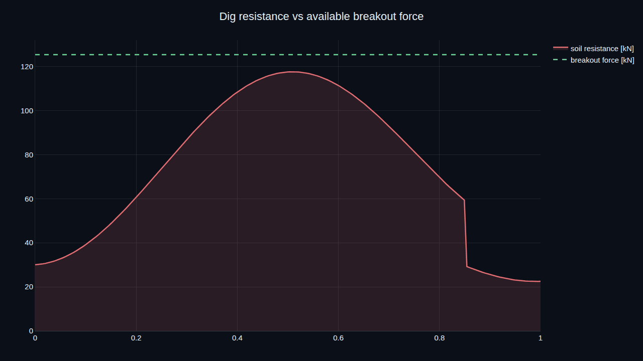 DjiniousLab
The notebooks are gated on worker-verified results, and the hydraulic actuator .djl is confirmed solving through the production canvas engine.
The arm is a planar 3-link model, the hydraulics are lumped cylinder-and-orifice elements rather than a distributed line model, and soil resistance is a scripted profile, not a soil-tool finite-element interaction. The coupled dig notebook uses a pressure-limited cylinder rate servo so the multibody integration stays robust while keeping real inertia, gravity and the hydraulic force ceiling. That is the fidelity machine design needs first: sizing cylinders and the pump, checking reach and breakout, sharing flow across actuators, and budgeting cycle energy — on your own machine numbers, before a full 3D multibody or a CFD hydraulic model.
Keep exploring
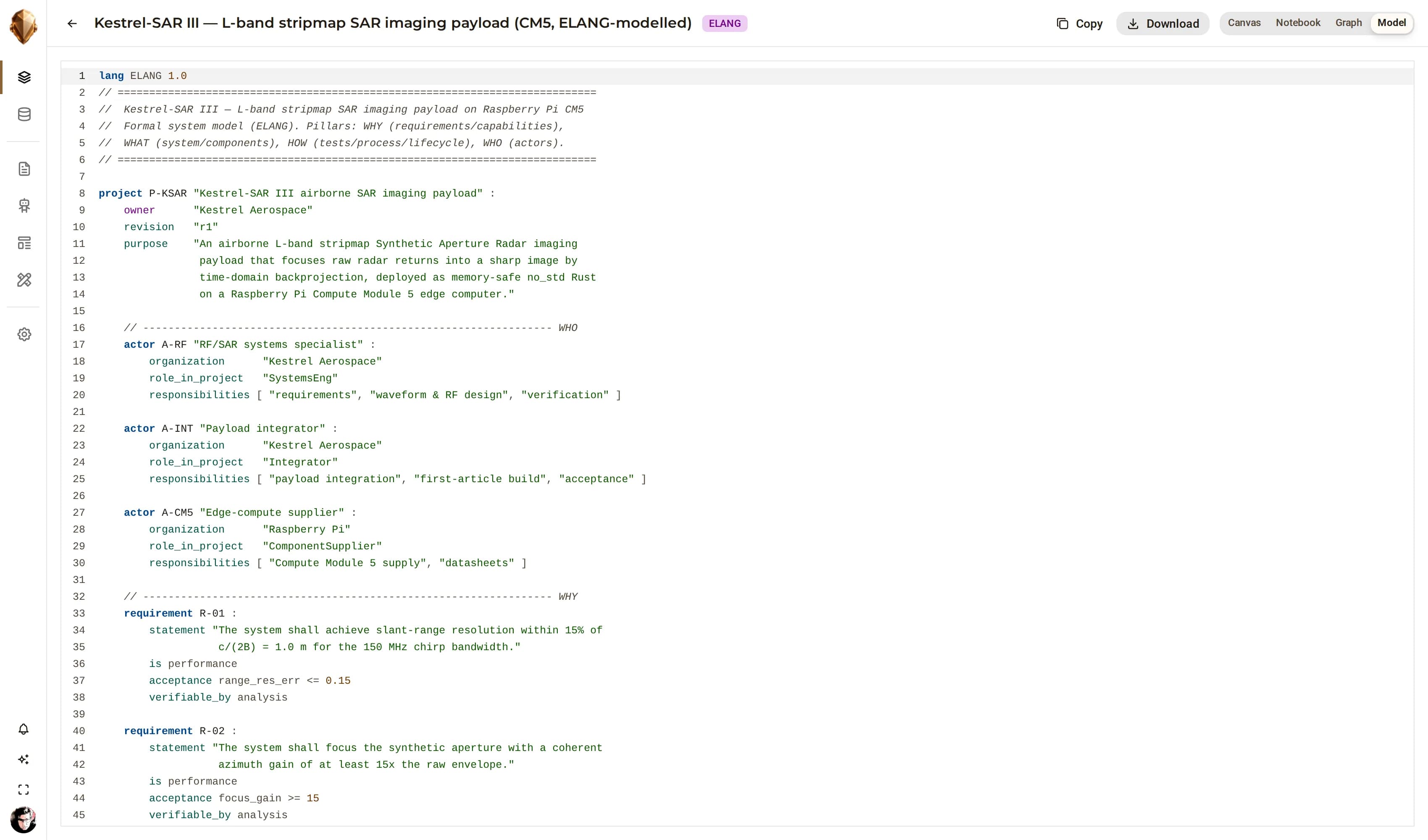 Industrial roboticsKronos Robotic Work CellA six-axis robotic work cell modelled end to end in ELANG as an audited reference — roughly a thousand lines carrying a functional-safety design to ISO 13849-1 Performance Level d, with every safeguard traced to the hazard it mitigates.
 DjiniousEngineering
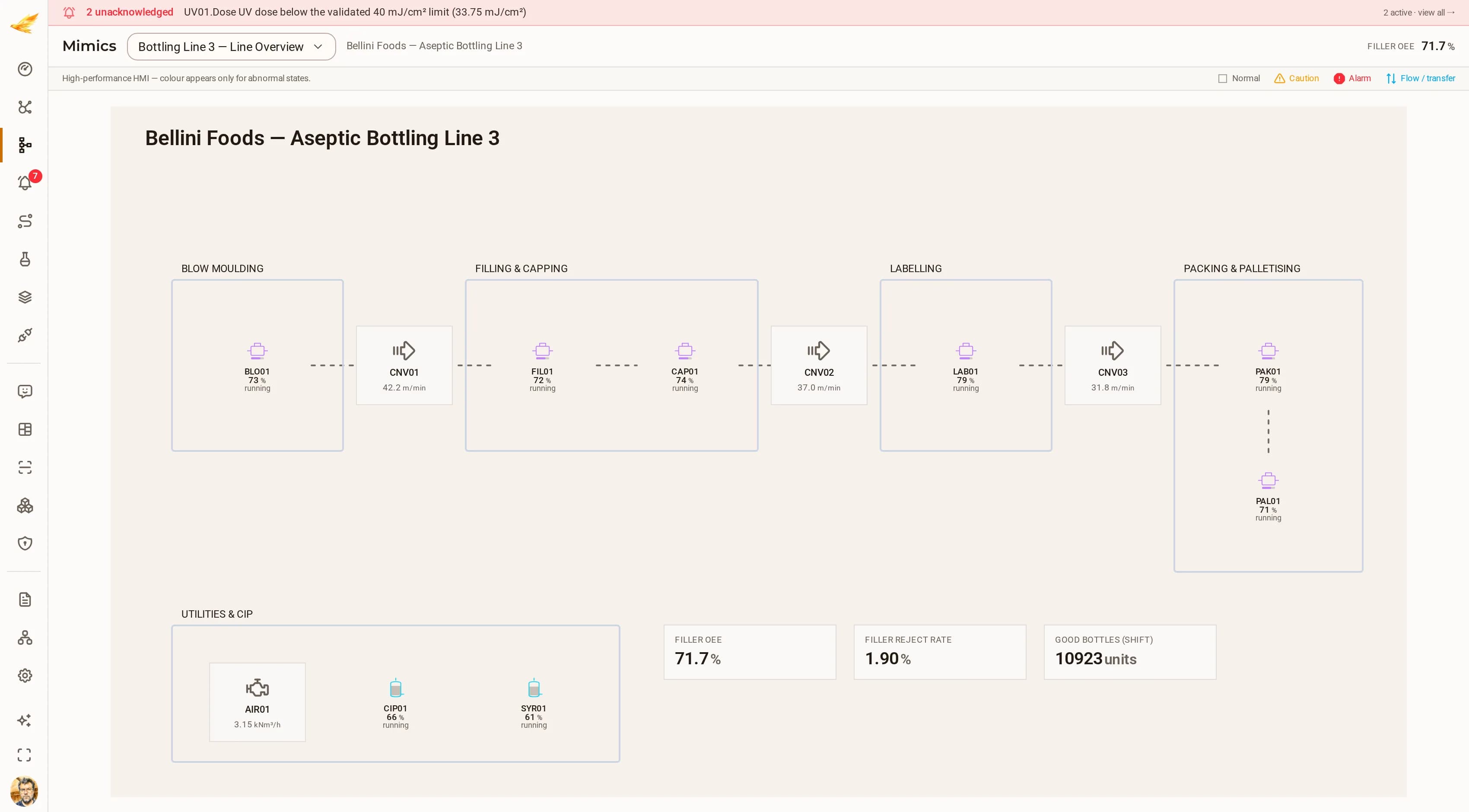 Food & beverage manufacturingBellini Foods — Aseptic Bottling Line 3A 24 000 bottles/hour aseptic PET line: blow moulding, aseptic filling, capping, labelling, case packing and palletising, with live OEE on every machine and its own utilities and CIP block.
 DjiniousCC
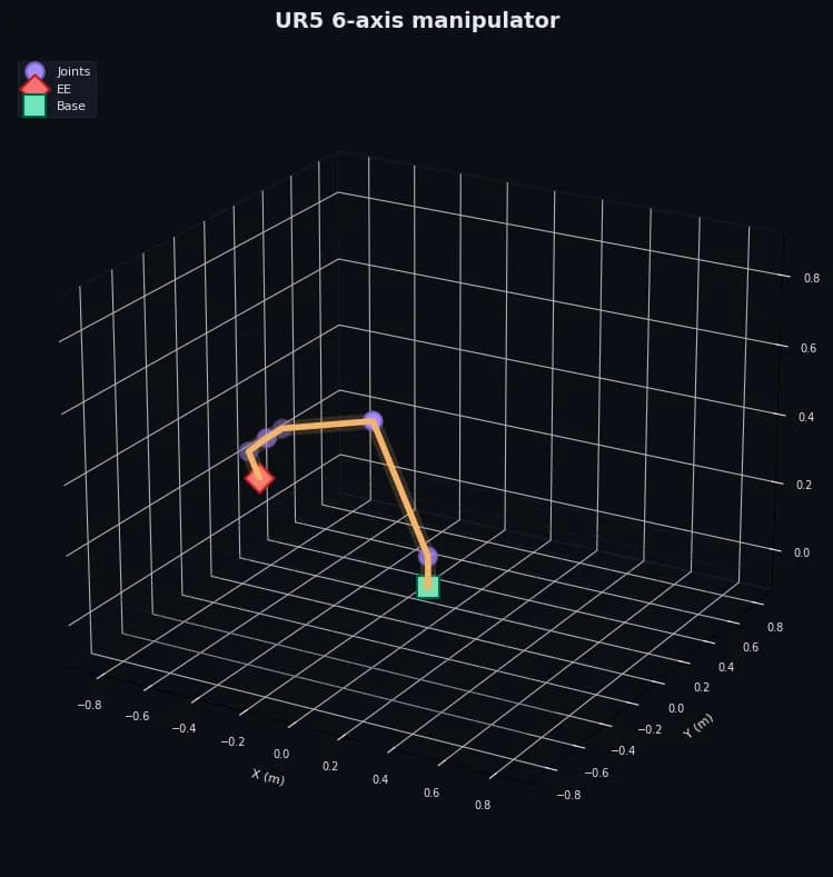 Industrial roboticsUR5 6-axis manipulatorA spatial 6-DoF UR5 arm as one multibody model — closed-form inverse kinematics driving a Cartesian end-effector path through per-joint PD control with gravity feedforward.DjiniousLab