 Djinious




Power electronics & FOC
From raw switching power electronics to smooth torque: a PWM buck converter and its averaged model, the PMSM dq machine, field-oriented control decoupling torque from flux, carrier PWM, a cascade speed loop, and field weakening — the inverter and control layer under an EV powertrain.
 DjiniousLab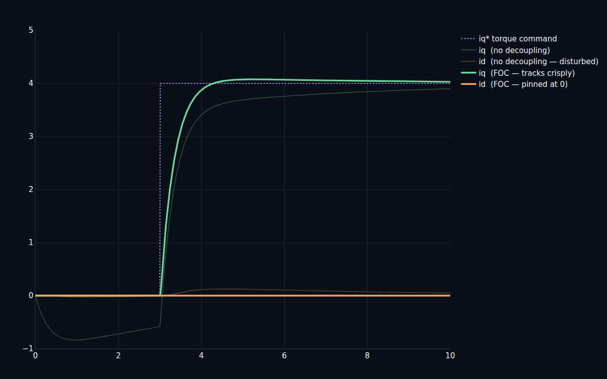
- buck output-voltage regulation error
- 0.034%buck output-voltage regulation error
- flux current under FOC torque step
- 0.0 Aflux current under FOC torque step
- rated drive efficiency
- 96.0%rated drive efficiency
- speed residual after a load step
- 0.285%speed residual after a load step
- design notebooks
- 10design notebooks
- requirements PASS
- 5 / 5requirements PASS
A motor switches at 20 kHz. Control has to make that smooth.
Power electronics is brutal at the bottom and elegant at the top. At the bottom, a converter chops DC on and off thousands of times a second and a motor is a tangle of cross-coupled three-phase currents. At the top, field-oriented control turns that into two clean knobs — torque and flux — you can command independently. This program walks the whole stack: the switching converter, the averaged model you design on, the dq machine, the FOC that decouples it, the PWM that realizes it, and the cascade speed loop that drives a load.
Everything starts as a square wave.
A buck converter regulates voltage by switching — full-on, full-off, thousands of times a second — and letting an inductor and capacitor average the result. The switched simulation shows the real thing: a triangular inductor-current ripple riding on the DC, and an output that settles to its setpoint within 0.034%. This is the raw material; every smooth quantity higher up is a controlled average of something that's actually chopping.
DjiniousLab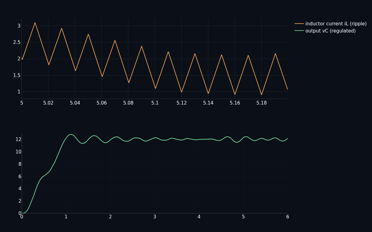
A three-phase motor's currents fight each other.
Transform the machine into the rotating dq frame and a spinning three-phase motor becomes two currents: id (flux) and iq (torque). But they're cross-coupled — command a torque-producing voltage and the flux current gets stirred along with it, and vice versa. Open-loop, a step in one axis disturbs the other by several amps. You can't independently set torque without first untangling that coupling.
DjiniousLab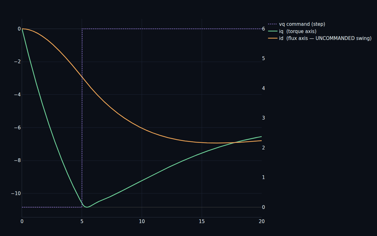 DjiniousLab
Turn the voltage command back into switching.
The controller computes a smooth dq voltage; the inverter can only switch. Inverse-Park plus carrier PWM turns the command into the actual on/off pole voltages, and the motor's inductance averages them back into a near-sinusoidal phase current. The smooth current the controller assumed and the chopped voltage the hardware delivers are two views of the same thing — the PWM is the bridge between them.
DjiniousLab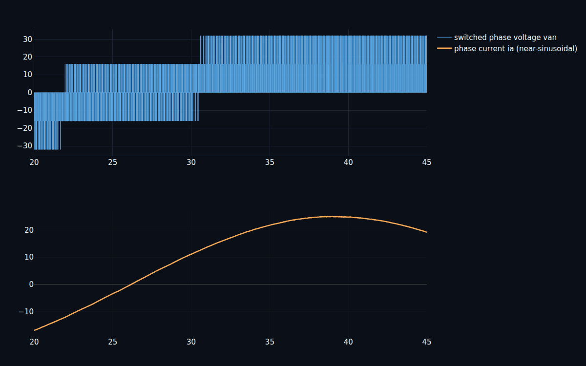
Wrap a speed loop around the torque.
Torque control is the inner loop; a real drive commands speed. A cascade adds an outer speed PI that asks the FOC torque loop for exactly the torque needed — so the motor tracks a speed reference and shrugs off a load-torque disturbance (a 3 N·m step recovers to 0.285% residual). Past base speed, field weakening drives the flux current negative to trade torque for range, extending usable speed well past where a fixed-flux drive runs out — at a rated efficiency of 96%.
DjiniousLab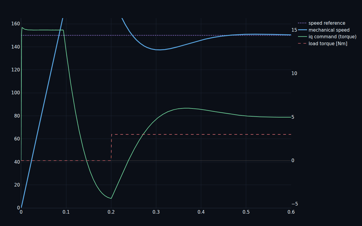
Every number re-derived at sign-off.
The V&V notebook rebuilds the converter, machine and controllers from scratch and re-derives the requirements, printing a PASS/FAIL board.
Result
- Buck output regulation: 0.034%
- Averaged-model fidelity: 0.257 V RMS
- FOC torque-step decoupling: iq 0.74% / id 0 A
- Speed-loop load rejection: 0.285%
- Rated efficiency: 96.0%
Requirement
- Buck output regulation: R-01 < 2%
- Averaged-model fidelity: R-02 < 0.5 V
- FOC torque-step decoupling: R-03
- Speed-loop load rejection: R-04 < 2%
- Rated efficiency: R-05 > 88%
Ideal switches, real control.
The deliverable is ten notebooks and the dossier — the models are switched ODEs with callbacks, not an acausal network. The switches are idealized (no device-level conduction/switching-loss physics beyond a lumped model), the thermal model is lumped, sensors are ideal with no estimation delay, and the PWM is carrier/sinusoidal rather than full space-vector with dead-time; the exact FOC decoupling is helped by the machine being non-salient. What the program does deliver is the complete drive stack — converter, averaging, dq machine, FOC, PWM, cascade speed control, field weakening — on reproducible numbers, the inverter-and-control layer one level below the EV-vehicle flagship.
Keep exploring
Related use cases
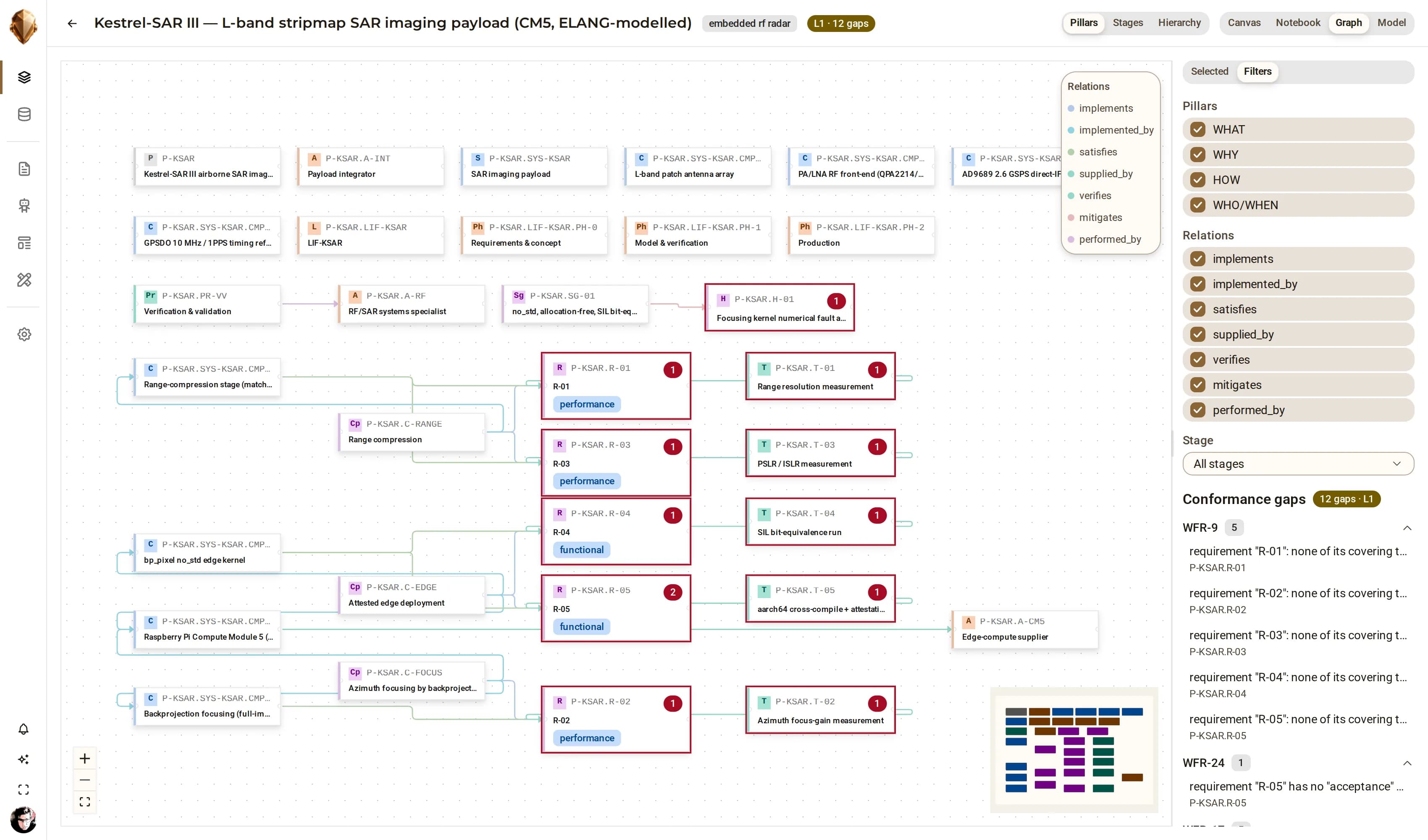 Grid-scale energySunnyGrid80 Solar-Storage PlantAn 80 MW photovoltaic plant with a 40 MW / 80 MWh battery energy-storage system and its grid substation, modelled in ELANG as an audited reference to UL 9540A and IEC 62443 — a system-of-systems where the interfaces carry as much of the design as the boxes.
 DjiniousEngineering
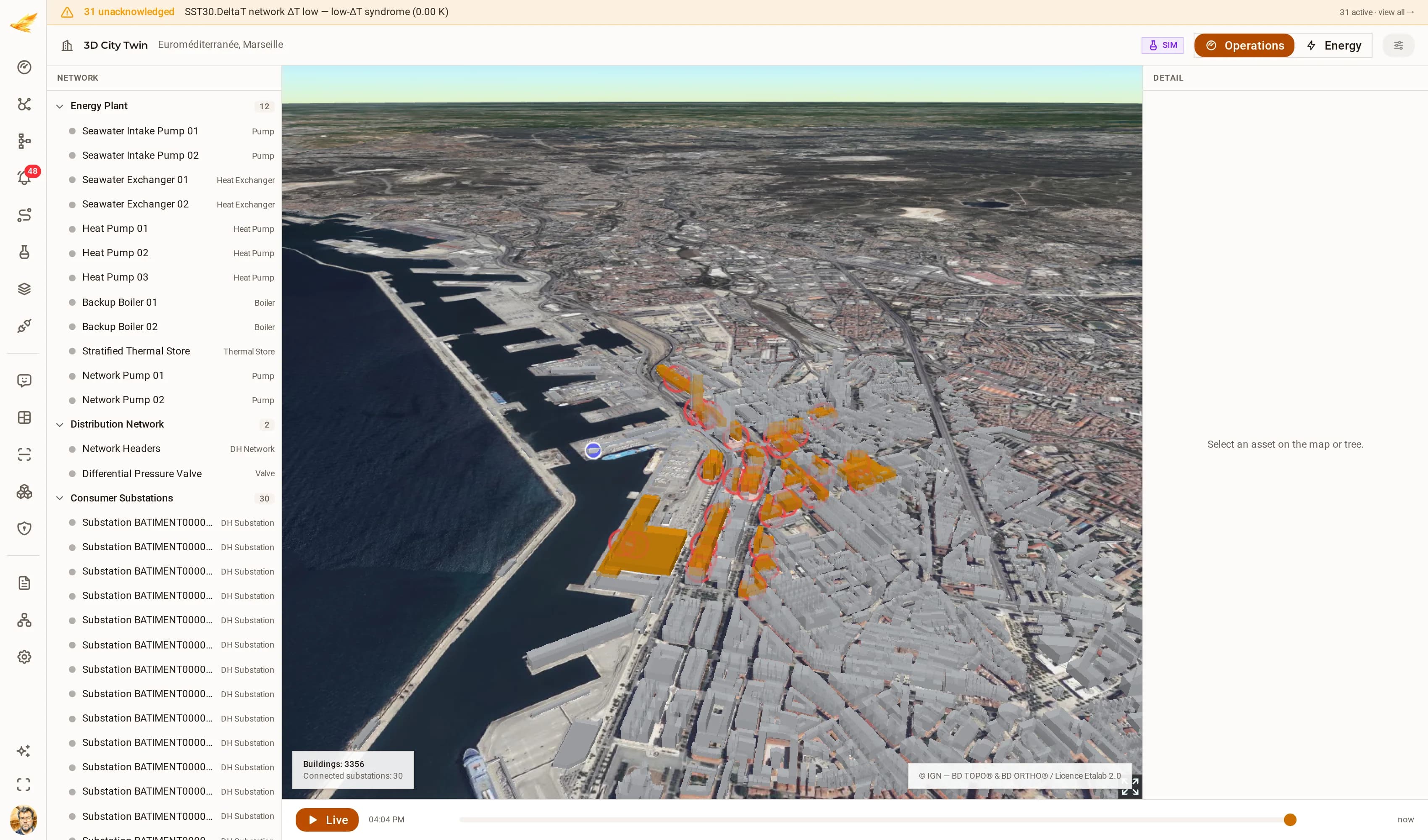 District energyEuroméditerranée District Energy NetworkA seawater-source district-heating network: two intake pumps and two seawater exchangers feeding three heat pumps, two backup boilers and a stratified thermal store, distributing through two network pumps and a differential-pressure valve to thirty consumer substations. The network is simulated; the city under it is not — every substation sits on its real IGN BD TOPO® building footprint in the Euroméditerranée quarter. It is a demonstration network on open data, not any operator's plant.
 DjiniousCC
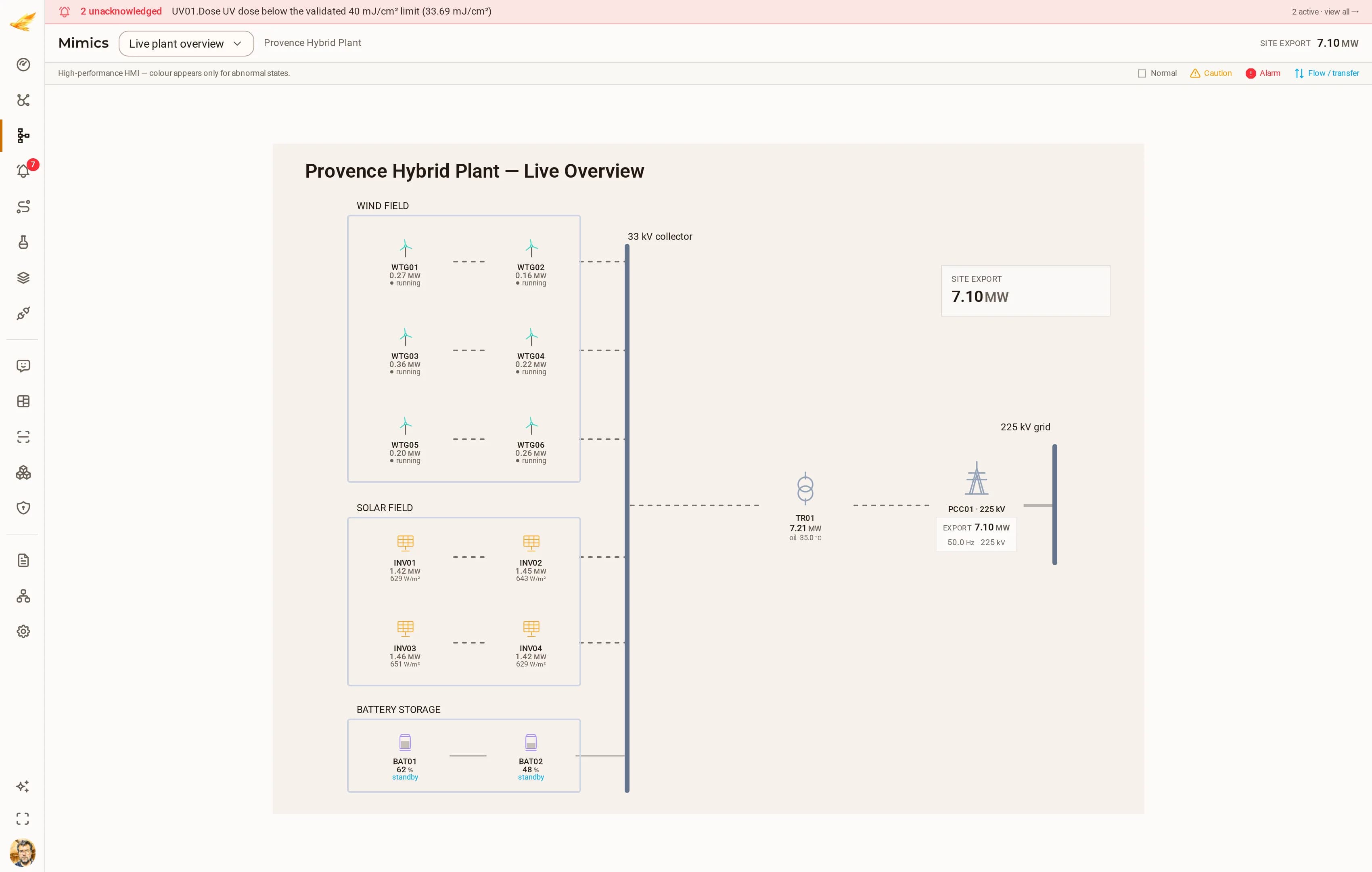 Renewable generationProvence Hybrid PlantA 120 MW hybrid plant: six wind turbines, four PV inverter blocks, two battery racks, the main 33/225 kV transformer, the grid connection point and a meteorological mast.DjiniousCC